To specify sequential circuits, we need to be able to make statements about how signals evolve over time. SMV uses a notation called temporal logic for this purpose. Temporal logic formulas are like formulas in ordinary boolean logic, except that truth value of a formula in temporal logic is a function of time. Some new operators are added to the traditional boolean operators ``and'', ``or'', ``not'' and ``implies'', in order to specify relationships in time.
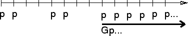
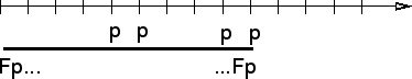
For example, the F operator is used to express a condition that must hold true at some time in the future. The formula F p is true at a given time if p is true at some later time. On the other hand, G p means that p is true at all times in the future. Usually, we read F p as ``eventually p'' and G p as ``henceforth p''.
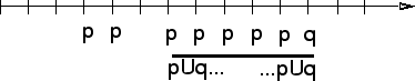
In addition, we have the ``until'' operator and the ``next time'' operator. The formula p U q, which is read ``p until q'' means that q is eventually true, and until then, p must always be true. The formula X p means that p is true at the next time.
Here are the exact definitions of the temporal logic operators, with example time lines showing the states when they hold true:
As an example, suppose we are designing a bus arbiter with two
``grant'' signals, ack1 and ack2. Among other things,
we want to specify that the two grant signals are never asserted at
the same time. In temporal logic, we would write G ~(ack1 & ack2).
The G operator is used to say that our specification should
hold true at all times. This is needed because SMV interprets ``assert''
statements to hold at the initial state of execution of the
program. If we wrote only ~(ack1 & ack2), SMV would interpret this
only to mean that both grants may not be asserted at time ![]() .
.
Return to our original example, and edit the four properties we specified so that they begin with the G operator. Make sure to undo the error we introduced in the previous section. You should have something like this:
module main(req1,req2,ack1,ack2)
{
  input req1,req2 : boolean;
  output ack1,ack2 : boolean;

  ack1 := req1;
  ack2 := req2 & ~req1;

  mutex  : assert G ~(ack1 & ack2);
  serve  : assert G ((req1 | req2) -> (ack1 | ack2));
  waste1 : assert G (ack1 -> req1);
  waste2 : assert G (ack2 -> req2);
}
Open the file and choose ``Prop|Verify all'' again to confirm that the properties we specified in fact hold true for all time. This is because the two logic equations we wrote for ack1 and ack2 hold implicitly for all time. Now let's write a more interesting temporal specification. Suppose we want to use our priority circuit as a bus arbiter. In addition to the above properties, we would like to avoid ``starvation'' of the low priority requester. That is, we don't want req2 to be asserted forever while ack2 is never asserted. Put another way, we want it to always eventually be true that either req2 is negated or ack2 is asserted. In temporal logic, we write ``always eventually'' by combining G and F. In this case we assert: G F (~req2 | ack2). Therefore, add the following specification to the program:
no_starve : assert G F (~req2 | ack2);
Now open the new version and verify the property no_starve. The property should be false, and a counterexample trace with one state should appear in the trace page. Notice that the state number is marked with ``repeat'' signs, thus: |: 1 :|. This is to indicate that the first state repeats forever. In this state, both req1 and req2 are asserted. Since req1 has priority, ack2 is never asserted, hence requester 2 ``starves''.
As an aside, you might also have observed that the signal ack1 doesn't appear in the trace. This is because SMV noticed that the property no_starve doesn't actually depend on this signal, so it left ack1 out of its analysis. The set of signals that a property depends on is referred to as the cone of that property. When you have selected a given property to verify, you can view the cone of that property by clicking the ``Cone'' tab. In this case, you'll notice that the signals req1 and req2 are listed as ``free''. This is because they are unconstrained inputs to the circuit, and thus are free to take on any values in their type. These signals each contribute one ``combinational'' variable to the verification problem. SMV must verify the property you specified for all possible combinations of these variables. Thus, it is generally best to keep the number of variables in the cone small, when possible.
Now, to prevent this starvation case, let's add a latch to the circuit that remembers whether ack1 was asserted on the previous cycle. In this case we'll give priority to requester 2 instead. To do this, add the following code to the program:
  bit : boolean;
  next(bit) := ack1;
The above means that bit is a boolean variable, and that the
value of bit at time ![]() is equal to the value of ack1
at time
is equal to the value of ack1
at time ![]() . This is how a state variable (or a register, if you like) is represented to SMV - as an equation
involving one time unit of delay.
Now, replace the definitions of ack1 and ack2 with the following:
. This is how a state variable (or a register, if you like) is represented to SMV - as an equation
involving one time unit of delay.
Now, replace the definitions of ack1 and ack2 with the following:
  if (bit) {
    ack1 := req1 & ~req2;
    ack2 := req2;
  }
  else {
    ack1 := req1;
    ack2 := req2 & ~req1;
  }
That is, when bit is set, we reverse the priority order. Note
that even though this may look like a sequential program, it really
represents two simultaneous equations. If you
like, you can write the same thing instead like this:
    ack1 := bit ? req1 & ~req2 : req1;
    ack2 := bit ? req2 : req2 & ~req1;
Now open the new version and verify property no_starve. It should be true. By the way, you might have noticed that we didn't specify an initial (i.e. reset) value for the register bit. In fact, SMV verified no_starve for both possible initial values. If you check the ``Cone'' panel, you'll notice that there are now two combinational variables (the inputs) and one state variable (the signal bit).